KMAX Functionality
Note
All KMAX versions have the same set of functions.
Versions vary not on the basis of function, but on performance and the type and number of network interfaces.
Graphical User Interface
Most people use KMAX through its graphical user interface. That interface is presented as a suite of web pages viewed through a web browser (such as Chrome, Firefox, or Safari) that is running either on the KMAX itself or on a convenient other machine, such as a laptop.
In addition to the functions described below, the KMAX graphical user interface contains ancillary web pages to perform network configuration, enable TLS/HTTPS, perform software updates, provide help and documentation, and so on.
KMAX Local Desktop
KMAX machines (with the exception of the KMAX-MM) support a local graphical desktop with a web browser.
In other words, you can connect KMAX to a video monitor (via HDMI, DisplayPort, or USB-C with video), a keyboard, and a mouse.
Tip
When you use the local desktop there is no need to configure the control/management network interface.
KMAX Managment/Control Network Interface - And Using KMAX From A Remote Browser
If you do not use a browser on the KMAX local desktop then you will need to configure (usually only once, when you first use KMAX) with standard network values, such as whether to use DHCP or a fixed IP address, DNS servers, NTP servers (optional.
Note
KMAX supports both IPv4 and IPv6.
On your laptop or desktop computer, you reach KMAX via a URL of the form:
http://<ip-address-of-the-kmax>/Tip
Note that
KMAX can be reached via HTTPS. However, you must first go in via HTTP to enable HTTPS.
You may have multiple browsers pointing at the same KMAX at the same time.
Note
KMAX is not intended to be a multi-user device. Rather, it may be controlled through one or more browsers, but that control is not independent - each browser has the same view of KMAX.
Application Programming Interface (API)
Overview of Packet Processing
Think of KMAX as if it were like a railroad classification yard.
Trains move from east to west and also from west to east - in other words, there is a bidirectional flow.
In KMAX, packets also move from data interface A to data interface B, and also in the reverse direction, from data interface B to data interface A.
KMAX treats these two directions as separate flows of packets, subject to separate and independent sets of impairments.
As a general rule, packets that enter via one of the data interfaces will exit via the other data interface. Between that entry and exit is where KMAX does its work. (Note that sometimes packets do not make it all the way through due to an impairment established by the user.)
Note
Much of the discussion below uses the word "packet". KMAX actually deals with Ethernet "frames" in which packets are embedded. KMAX can handle large Ethernet frames - up to roughly 9000 bytes. (The exact number depends on the Ethernet chipset used by the platform on which KMAX is running.)
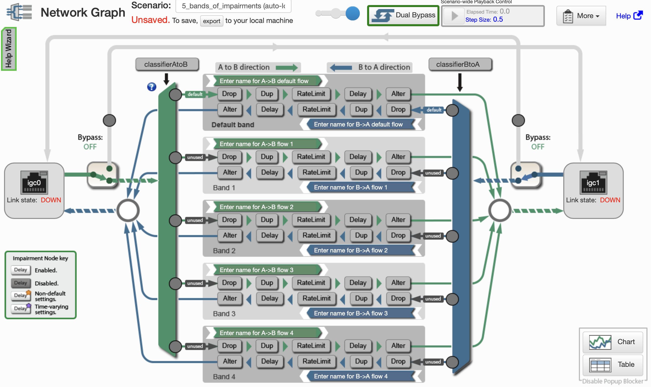
In the diagram below, we can see the overall packet processing flow in KMAX.
-
Packets enter via either the interface on the left (in the diagram, this is "igc0") or the interface on the right ("igc1"),
-
Immediately after entry, an incoming packet hits a "bypass switch". This switch can divert the packet around the KMAX core of classifiers and impairments. There is a bypass switch for each direction of packet flow. This bypass function is useful for doing ad-hoc A:B comparison testing where the user is testing the effects of having impairments ON versus impairments OFF.
-
If a packet is not sent on the bypass, that incoming packet enters a packet classifier (shown as tall green and blue bars to the left and right sides of the core matrix of impairments such as Drop, Duplication, Delay, etc.)
These classifiers examine the packet headers (at many protocol levels, from Ethernet and VLAN headers, MPLS, IPv4, IPv6, UDP, TCP, and more) against user-specified criteria. The result of these classifiers is that the arriving packet is sent into one of several bands (also called "flows"). Packets that match no criteria are sent into a default band.
-
The classifiers deliver each incoming packet into one of the band/flows where that packet is run through a sequence of impairment stages. These stages will be described in more detail later on.
-
After passing through the impairment stages the packets are sent to the outgoing network interface.
Note
Users may change many of the impairment parameters "on the fly" - changes take place immediately with no need to stop or restart the KMAX. The KMAX software has several options pertaining to the transitional effects as impairment parameter values are changed.
In the diagram below, you may notice some small grey circle-discs. Those are "pacman" gauges that display the amount of traffic flowing through that part of the KMAX packet processing graph.
KMAX Impairment Graph Screen
(Click to expand image.)
Bands (Flows)
In KMAX, bands (also called flows) are uni-directional sequences of impairments. Packets passing through a band go through a series of impairment stages. (See Impairments for details.)
- Packet Drop
- Packet Duplication
- Rate Limitation
- Delay
- Packet Alteration
These bands are clearly seen in the Impairment Graph screenshot above.
Each of these stages is under user control, and each has several parameters; many of those parameters may be run through a pattern of changes via a Waveform.
The Bypass mechanism allows incoming packets to avoid the classifiers and bands.
Packet Classification
During packet classification, each incoming packet is run past a sequence of user-defined filters.
Each filter examines the packet and, if the packet matches the filter's criteria, that packet is sent into the input side of a band designated by that filter.
Thus, for example, a filter might be defined to match all IPv6 packets going to a block of IPv6 addresses, and if there is a match, those packets would be sent into Band #2.
If the incoming packet matches no filters, then that packet is sent into the default band.
Note
Because the filters are evaluated sequentially, the order of active classification filters is important.
Pre-Written Classification Filters
We have written a number of Classification Filters and placed them into a library. Users may use these as prototypes, typically by changing IP addresses and port numbers as appropriate for the user's network configuraiton and traffic.
For example, there is a pre-written filter to send packets in TCP streams into a given band. The user activates a copy of that pre-written filter and inserts the user's own parameters, such as the IPv4 or IPv6 source and/or destination addresses and TCP port numbers.
Here is the current list of pre-written classifiers:
- ARP packets, using PCAP syntax
- ARP packets: EtherType field is 0x0806
- All IPv4 packets
- All IPv6 packets
- All Packets
- An IPv6 packet with a flow label between 0x5A5 and 0xDE7F
- Any TCP or UDP packet
- Any TCP packet
- Any UDP packet
- DHCP/UDP client requests over IPv4: src port 68 and dst port 67
- DHCP/UDP server replies over IPv4: src port 67 and dst port 68
- Destination MAC 01:02:03:04:05:06
- ICMP echo reply (PING response)
- ICMP echo request (PING request)
- ICMP packets
- IPv4 TCP packets with a dst port of 80 (HTTP)
- IPv4 TCP packets with a src port of 80 (HTTP)
- IPv4 packets with IP total length < 1024 bytes
- IPv4 packets with IP total length < 128 bytes
- IPv4 packets with IP total length < 256 bytes
- IPv4 packets with IP total length < 512 bytes
- IPv4 packets with IP total length < 64 bytes
- IPv6 packets that are fragments
- IPv6 packets with IP total length < 1024 bytes
- IPv6 packets with IP total length < 128 bytes
- IPv6 packets with IP total length < 256 bytes
- IPv6 packets with IP total length < 512 bytes
- IPv6 packets with IP total length < 64 bytes
- Likely VoIP: IPv4 UDP, 0x10 QoS bit
- Likely VoIP: IPv4 UDP, < 256 bytes, QoS ignored
- Likely VoIP: IPv4 UDP, < 256 bytes, Qos bits off
- OSPF over IPv4
- OSPF over IPv6
- Source MAC 01:02:03:04:05:06
- Spanning tree (Destination MAC 01:80:C2:00:00:00)
- The last fragment in a fragemented IPv6 packet
- UDP packets with a dst port of 5060 (SIP)
- UDP packets with a dst port of 53 (DNS)
- UDP packets with a src port of 5060 (SIP)
- UDP packets with a src port of 53 (DNS)
- tcp_dst_addr_1_2_3_4
- tcp_src_addr_1_2_3_4
A Word About "Bursts"
In the real world, network flaws often occur in short bursts. Lightning or branches waving across a microwave (or laser) link cause short bursts of packet loss. Congestion in routers and switches along a network path causes bursts of packet delay and loss. Satellites may suffer from high loss rates when it is raining on ground stations, or total loss when a satellite is blinded by the reflection of the sun from the Earth's surface or when a satellite transits the sun as seen by a ground station.
KMAX uses a probability chain model to emulate bursts. The KMAX model is an extension of the Gilbert–Elliott model.
The IWL burst model has three principal parameters:
-
Burst Probability percentage - The probability that the impairment will be repeated for a packet that arrives within the burst window of a previously impaired packet.
-
Burst Window - A packet that arrives within the burst window duration after an impaired packet will be a candidate for burst impairment.
-
Burst Skew - When enabled, the burst probability starts at the specified value, then falls linearly to zero when the burst window expires.
Impairments
The names of the impairments, below, are largely self descriptive.
However, each of these impairments has many options and parameters (with many of those parameters controllable via an attached Waveform control.)
Throughout these impairments are options (and parameters with Waveform controls) to perform various forms of burst behavior.
Packet Drop
The Packet Drop impairment is the simpliest of the impairments: It simply discards a certain percentage of pseudo-randomly selected packets.
There is also a burst facility to emulate the way that real-life packet loss often comes in short bursts.
Packet Duplication
Packet duplication is also a simple impairment. It simply duplicates a certain percentage of pseudo-randomly selected packets.
There is also a burst facility to emulate the way that real-life packet duplication often comes in short bursts.
Rate Limitation
Rate limitation is very complex.
The target rate that is specified is, at best, an approximation that KMAX will approximately achieve over a span of time.
There are two basic modes of rate limitation, "bit clocking" and "token bucket". The former is appropriate for use on serial hardware links where unused capacity is forever lost. The latter is appropriate for link that contain intermediate devices that contain buffers and queues, and in which unused past capacity may be a credit that allows short term bursts above the specified data rate (but over the longer term the average rate approximately as specified.)
Rate limitation requires KMAX to maintain queues of packets that are being delayed. Those queues are of finite (but user specifiable size). When theose queues exceed that size, packets are discarded.
Rate limitation also needs parameters to specify how many bits of packet wrappers (headers) are to be excluded from the rate limit calculations.
Delay (Fixed and Variable Latency)
Delay, also known as latency, is surprisingly complex.
The KMAX delay impairment encompasses several aspects:
-
Fixed latency - This is a fixed amount of time used to delay selected packets.
-
Variable latency (jitter) - This is a variable amount of time that is added to the fixed delay of selected packets.
-
"Dam bursting" - A queue is used to hold packets being delayed. KMAX can hold the release (transmission) of delayed packets and then release the accumulation as a sudden burst of those waiting packets. This results in the network equivalent of a "water hammer" that can occur in water pipes and thus stresses the ability of downstream network devices to handle the sudden load.
-
Packet resequencing - As part of the dam bursting behavior, KMAX can change the order of release so that a packet sequence of (for example) A, B, C, D, E is changed to D, A, C, B, E. This can reveal sensitivities and flaws in downstream devices (usually in the destination endpoint device) to the arrival of packets whose sequence has been changed.
Note
The variable latency/delay is a pseudo-random amount of time that is calculated for each selected packet. This ought not to be conflated with delay parameter changes made by a Waveform attached to the various delay/latency parameters. Waveforms can impose "low frequency" (comparatively slow) changes to latency while the variable latency settings are comparatively "high frequency".
Packet Alteration
The packet alteration impairment has three aspects:
- Bit corruption - This aspect flips bits in the aggregate flow of bits contained in packets. Because even a single packet may contain more than ten thousand bits, the user specified percentages are generally quite small.
- Packet corruption - This aspect flips bits in a user specified percentage of packets.
- Packet transformation - This aspect is usually disabled and requires its own documentation.
Note
Packet corruption will often invalidate any checksums or CRCs, such as the IPv4 or IPv6 header checksum, or the TCP or UDP data checksum.
However, the packet corruption impairment does not result in an incorrect Ethernet CRC. That CRC is recomputed by the KMAX Ethernet chipsets as the packet is sent on the outgoing network interface.
Waveforms
Waveform Example
Click to expand.
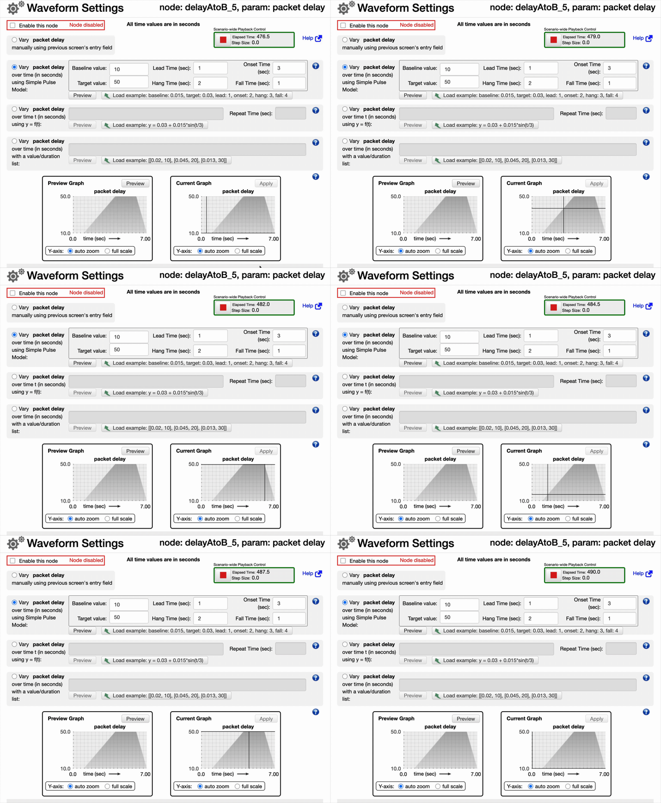
Waveforms in KMAX are a means to change numeric impairment parameters over a span of time ranging from less than a second to an hour (or more.) When that span is complete, the waveform starts again.
Each waveform contains a time-based pattern that changes the value of the parameter to which the waveform is bound. This pattern can be defined by the user in various ways.
The pattern shown here in the the Waveform Example is a repeating pattern. This example is attached to the fixed delay parameter of the Delay impairment. (That impairment stage also includes several other parameters to facilitate, for example, variable delay.)
- The pattern begins with a baseline delay of ten seconds (this is a long delay, ten milliseconds would be 0.010.)
- This baseline is held for one second.
- Then the delay rises over a span of three seconds to a target value of fifty seconds (again, this is a very long time, for fifty milliseconds one would enter 0.050.)
- This target delay is held for two seconds.
- Then, over a span of one second, the delay falls from that target back to the baseline.
- The cycle then repeats.
Waveforms are sometimes called "low frequency", as compared to the short-term (often as short as milliseconds) time spans that are involved in things such as variable packet delays in the Delay impairment.
Thus, for example, a waveform could change the rate of packet drop in the Drop impairment so that the rate climbs from 0% to 20% over a span of thirty seconds and then drops back to 0% over a span of one second.
Note
A useful use of Waveforms is to subject a TCP connection to a sawtooth pattern of packet loss or delay (via the packet Drop or packet Delay impairments) so that the loss or delay increases over a span of thirty to sixty seconds from a low baseline to a higher value (such as 50% loss or 500milliseconds of delay), holds that status for a few seconds, and then quickly drops back to the baseline. This puts significant stress on the TCP protocol stacks' ability to detect congestion, deploy their congestion avoidance mechanisms, and then return to normal.
All waveforms begin and stop together. In other words, their start times are synchronized with one another.
We have written a short article on Waveforms in KMAX
Scenarios
Scenarios are packages of KMAX impairment configurations (including classification filters) that may be loaded (and, if desired, modified), and used
Here is a partial list of pre-installed scenarios.
- Emulates 3G/4G extreme Round Trip Time (RTT) (Load and Go)
- Emulates 3G/4G high jitter (Load and Go)
- Emulates 3G/4G high packet loss (Load and Go)
- Worst case 4G/LTE, 3G, throughput
- Extreme RTT, jitter, and Pkt Loss emulation
- A KMAX scenario with 1 band, and 2 flows in each band.
- Emulates worst case 3G conditions (Load and Go)
- Emulates worst case 4G/LTE conditions (Load and Go)
- Emulates impairments likely to occur for a mobile app that connects to the cloud (Load and Go)
- A KMAX scenario with 1 band, and 2 flows in each band.
- A KMAX scenario with 1 band, and 2 flows in each band.
- Emulates impairments likely to occur for a mobile app that connects to the cloud (Load and Go)
- Emulates impairments likely to occur for a mobile app that connects to the
- A KMAX scenario with 1 band, and 2 flows in each band.
- Emulates impairments likely to occur for a mobile app that connects to the cloud (Load and Go)
- Emulates impairments likely to occur for a mobile app that connects to the cloud (Load and Go)
- This scenario emulates the ATM protocol running over a T1 link between New York and London.
- Auto-assigns each detected client (up to 31) to its own band,
- A KMAX scenario with 1 band, 2 flows in each band, and one node per flow.
- A KMAX scenario with 1 band, and 2 flows in each band.
- A KMAX scenario with 2 bands, and 2 flows in each band, with a classifier.
- A KMAX scenario with 3 bands, and 2 flows in each band, with a classifier.
- A KMAX scenario with 32 bands, and 2 flows in each band, with a classifier.
- A KMAX scenario with 4 bands, and 2 flows in each band, with a classifier.
- A KMAX scenario with 5 bands, and 2 flows in each band, with a classifier.
- A KMAX scenario with 6 bands, and 2 flows in each band, with a classifier.
- A KMAX scenario with 64 bands, and 2 flows in each band, with a classifier.
- This scenario emulates a multi-party audio conference call
- To be used with a corner case test plan.
- A 4-interface KMAX scenario with a 1:3 multiplexor
- A KMAX scenario with 1 band, and 2 flows in each band.
- A KMAX scenario with 1 band, and 2 flows in each band.
- A KMAX scenario with 1 band, and 2 flows in each band.
- A KMAX scenario with 1 band, and 2 flows in each band.
- A KMAX scenario with 1 band, and 2 flows in each band.
- A KMAX scenario with 1 band, and 2 flows in each band.
- A KMAX scenario with 1 band, and 2 flows in each band.
- A KMAX scenario with 1 band, and 2 flows in each band.
- Emulates Four different LPWAN IoT networks
- A KMAX scenario with 1 band, and 2 flows in each band.
- A KMAX scenario with 1 band, and 2 flows in each band.
- A KMAX scenario with 1 band, and 2 flows in each band.
- A KMAX scenario with 1 band, and 2 flows in each band.
- Emulates ZigBee and Z-Wave for Home Automation
- Media player at home, receiving a satellite stream, and sending a DSL control stream.
- Drop 0.1%, Dup 0.01%, Rate 3Mbps, Delay 123ms, Jitter 53ms.
- Drop 0.21%, Dup 0.035%, Rate 3Mbps, Delay 181ms, Jitter 68ms.
- Drop 0.66%, Dup 0.05%, Rate 3Mbps, Delay 348ms, Jitter 175ms.
- Drop 0.004%, Dup 0.01%, Rate 50Mbps, Delay 33ms, Jitter 4ms.
- Drop 0.12%, Dup 0.035%, Rate 50Mbps, Delay 50ms, Jitter 16ms.
- Drop 0.35%, Dup 0.05%, Rate 50Mbps, Delay 83ms, Jitter 49ms.
- Drop 0.004%, Dup 0.01%, Rate 26Mbps, Delay 9ms, Jitter 3ms.
- Drop 0.13%, Dup 0.035%, Rate 26Mbps, Delay 52ms, Jitter 17ms.
- Drop 1.1%, Dup 0.05%, Rate 26Mbps, Delay 348ms, Jitter 175ms.
- A KMAX scenario with 4 Interfaces.
- This scenario emulates packet drop and packet jitter on a noisy factory floor
- An example of time-varying drop and delay using the value/duration waveform specification.
- Simulates impairments in a customers WiFi connection, and in the WAN
- Emulates a site-to-site handoff for a device. (Load and Go)
- This set of impairments provides a restricted-bandwidth link from an operator control station to a robot.
- This scenario emulates a communication link via a satellite in geosynchronous orbit at 36,000km
- Simulates failover from a high bandwidth WAN to a low bandwidth WAN
- A stress test to validate KMAX
- A KMAX scenario with 1 band, and 2 flows in each band.
- A KMAX scenario with 1 band, and 2 flows in each band.
- A KMAX scenario with 1 band, and 2 flows in each band.
- Filter packets into separate flows for RTP, RTCP, and SIP signaling, 4_band.
- Filter packets into separate flows for RTP, RTCP, and SIP signaling.
- Emulates corporate LAN, WAN connection to remote offices, with voice gateways
Note
KMAX may be configured to load a given scenario when it starts. This is useful when running KMAX in a "headless" environment where access to the graphical user interface would be difficult.
Bypass Mode
To facilitate comparison testing, KMAX supports a pair of packet bypass pathways (one for each direction of packet flow.) When a bypass is enabled, incoming packets are diverted around the classifiers and bands, so that those packets (actually Ethernet frames) pass through the KMAX with no disruption and minimal delay.
Note
The typical time for a packet to pass through KMAX is quite short - typically less than a hundred microseconds, often much less, depending on the platform on which KMAX is running.
Traffic Graphing and Charting
The KMAX user interface allows the user to open additional pages that display statistics of the traffic flowing through the KMAX. One of those pages presents these statistics as a real-time graph, the other displays the values as numbers.
Documentation
Most KMAX documentation is on the device itself (as well as online on IWLs website).